Flexible PCBs Are Made
The manufacture of flex PCBs is more complicated than rigid ones. They have more layers, are thinner, and require a special base material. Additionally, they can be curved to conform to the shape of an enclosure, or a panel. They are therefore more expensive to produce, and they must have a design that supports expansion and contraction without breaking. These requirements have resulted in tighter manufacturing rules and the need for smaller conductor spacing. To make the most of a flexible PCB, designers need to carefully consider these guidelines while creating their layout.
The first step in the production of a flex circuit board is to create a structure diagram and stack-up. These documents show exactly how the traces will look on the final product and help determine the impedance of the circuit. The structure diagram also needs to include any labels, markings, or identifiers the flex circuit will need to have.
Next, the flex PCB must be etched and cut to prepare it for the copper layer. This process requires a laser that can create the fine lines required by a flexible pcb board. In the past, razor blades were used to cut a PCB, but lasers offer much greater accuracy and precision. This allows for a flex circuit to be designed with smaller traces, which in turn reduces the number of connections needed and improves electrical performance.
How Flexible PCBs Are Made
Once the etching and cutting are complete, the flex PCB must be panelized. This is a process in which the circuit boards are grouped together into large panels for easier assembly. This can greatly increase the efficiency of a flex circuit assembly, especially in “pick-and-place” assembly processes. It also helps to protect the ultra-thin material cores from damage during transport and storage.
Finally, the flex PCB must be soldered. This is a delicate process that requires specialized equipment and training. It must be performed with extreme care to prevent any kinks or creases in the PCB, as these can lead to failed electrical tests and reliability problems.
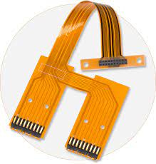
The main components of a flex circuit are the copper layers, the insulating film layer, and the coverlay. Copper is a good conductor because of its excellent electric properties and superior heat dissipation capabilities. The insulating film is typically polyimide, which offers excellent adhesive properties. It also provides a smooth surface for soldering. For high-speed applications, a flex circuit will often have a thicker copper layer to support higher speeds and reduce the possibility of signal loss or interference.
For lower speed signals, a thinner layer can be used to save on materials and manufacturing costs. A flex circuit can also be reinforced with stiffeners for extra strength and stability. However, a rigid stiffener can interfere with the circuit’s ability to bend, and it may reduce the PCB’s flexibility. Therefore, a flex PCB should be designed with a good bend radius and adequate stiffeners for a reliable, long-term use.